This article picks up immediately from the end of Using A Solderless Breadboard. If this is your first project, please read the intro article before you continue and make sure that you are comfortable with the concepts and techniques. If you are already familiar with breadboarding, note that the level of detail in this article is meant to guide complete beginners, so please be a little patient.
I will walk you through the setup of a complete circuit. When you are done, you will have something that can be committed to a soldered build on perfboard or a PC board.
Here's the basic circuit that we will set up:
This is a more complex schem than the LED demo in the intro, but it's still only a dozen parts including the battery...not too tough. I have purposely not included jacks, stomp switch or power switching in order to keep it simple; we'll add those later. The only things to note right now are:
-
Where wires cross in a schematic but Don't connect, you'll see this:

-
Where wires cross or join in a schematic and Do connect, you'll see this:

-
The Ground symbol
 is not a connection to the Earth; it's the
reference point from which all voltages in the circuit are measured. All
points in the circuit that have or share the Ground symbol are connected. If this is
not clear yet, you'll get the idea as I walk you through the build.
is not a connection to the Earth; it's the
reference point from which all voltages in the circuit are measured. All
points in the circuit that have or share the Ground symbol are connected. If this is
not clear yet, you'll get the idea as I walk you through the build.
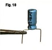
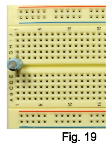
So let's go! Trim and form the leads of a 2.2 mf. ("microfarad") electrolytic capacitor, following the convention of leaving 1/4" to 5/16" of lead length for insertion in the board. Electrolytic caps are most often polarized; on radial-case types like this one, a black band marks the negative side (Fig. 18.) I formed the leads to span five holes, but again, this is arbitrary. You may want to follow my directions and layout this time around; once you have the idea, you're free to do whatever works. Similarly, I am working from left to right on the board, but that's not engraved in stone, either. Plug in the cap with the negative side toward the power rails, since that's where the guitar input jack will connect later (Fig. 19.) I have it located between indexes E-1 and G-1. You don't have to use exactly the same locations I do. However, if following my footsteps (bear tracks?) helps to build your confidence and avoid mistakes, go for it.
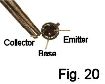
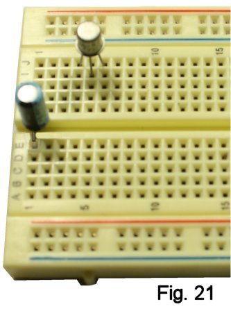
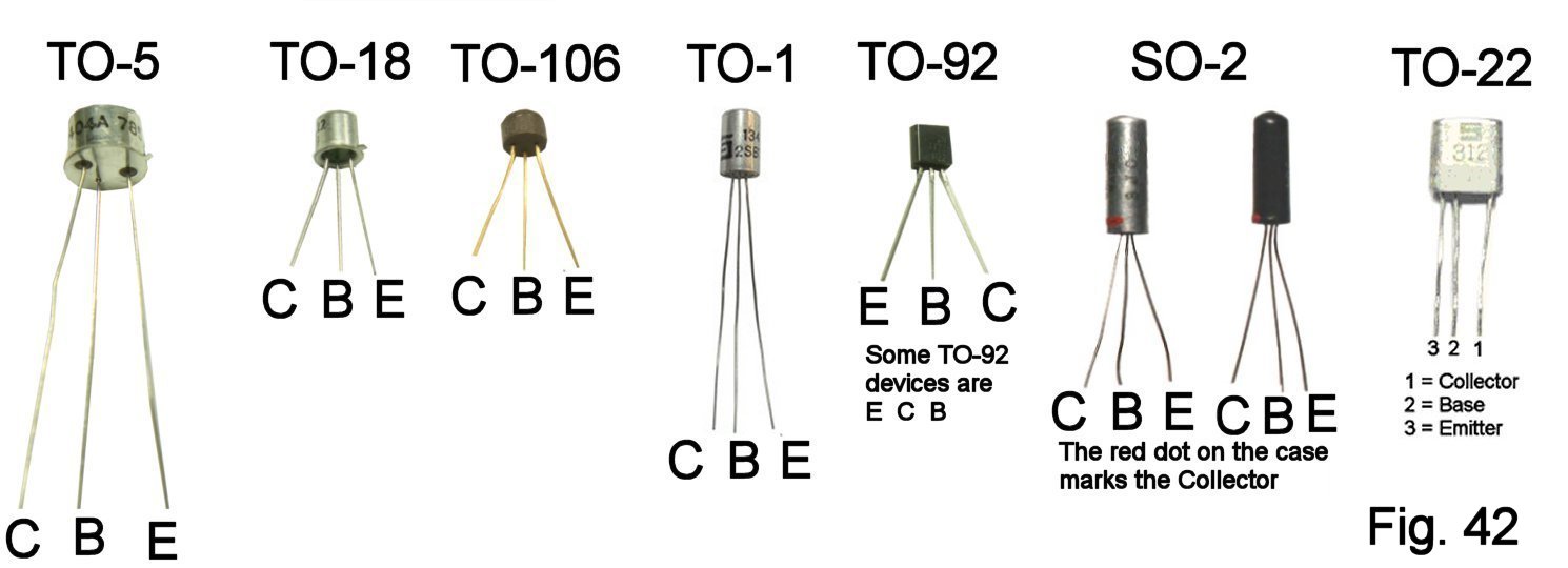
Now add transistor Q1. It has three leads: Collector, Base and Emitter, identified as C, B and E in the schem. I suggest either a 2N2222A or a BC108, both of which come in a metal can called a TO-18 package. In this style, the leads form a triangle, and the can has a tab next to the Emitter (Fig. 20.)
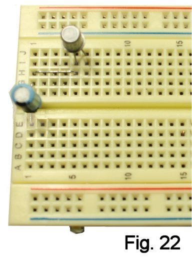
I plugged this device into indexes J-4, I-5 and J-6 with the tab on the can to the left (Fig.21.) The choice was arbitrary, but it turned out to be perfectly workable as I added more parts and connections. When you get to "rolling your own," if your first choice of a location doesn't pan out, back up and try somewhere else! Now bend a short, bare-wire jumper to span five holes and plug it into indexes H-1 and H-5 (Fig. 22.) Fig. 23 shows the connection that you have made. Got the idea?
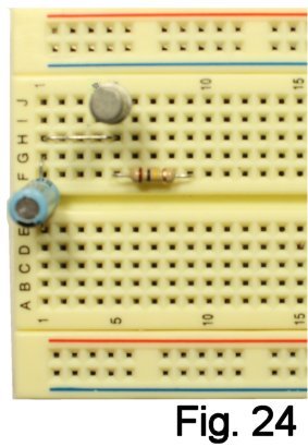
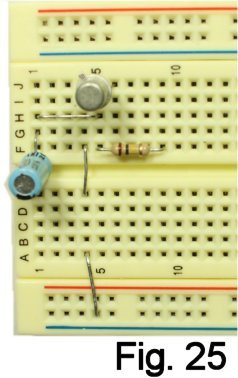
Now complete the connections to the Base of the transistor by adding a 100K resistor between indices F-5 and F-9 (Fig. 24.) The color code is Brown, Black, Yellow, Gold. The Emitter of transistor Q1 needs to get to the ground bus, so add two jumpers from indices E-4 to F-4 and A-4 to ground (Fig. 25.) Figure 26 shows these connections.
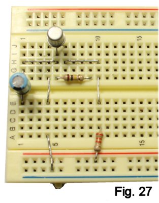
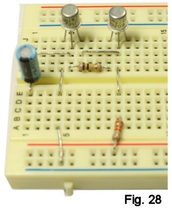
A 33K (Orange, Orange, Orange, Gold) resistor needs to connect from the Collector of Q1 to the positive power supply bus. Plug it in from there to index B-10 and add two jumpers, E-10 to F-10 and H-10 to H-6 (Fig. 27). Transistor Q2 goes in next. Since its Emitter needs to connect to one side of the 100K resistor, that pin (the one near the tab) logically goes in at index J-9 (Fig. 28). Putting the Base Q2 in the next column connects it to the Collector of Q1. Figure 29 shows where we are.
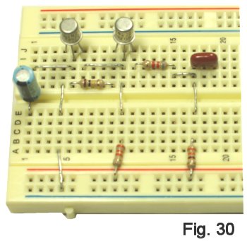
Last components before we add the pots: The 8.2K (Gray, Red, Red, Gold) connects to the Collector of Q2. I know it will meet with one side of the 330 ohm, so I run it horizontally starting from index H-11. This isn't the tightest use of space, but it does keep the layout clean and easily visible. 330 ohms (Orange, Orange, Brown, Gold) goes from the positive supply bus to index B-17 and two jumpers connect it to index G-15. A .01 mf. film capacitor (marked "103") starts at H-17 and should terminate at index H-19. It is not polarized and can go in either way (Fig. 30). We are getting close (Fig. 31.)
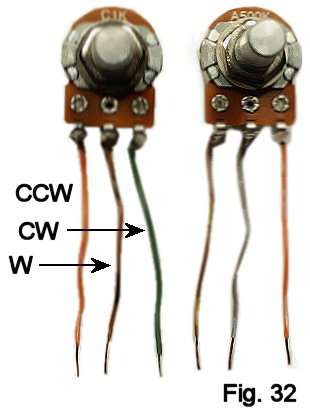
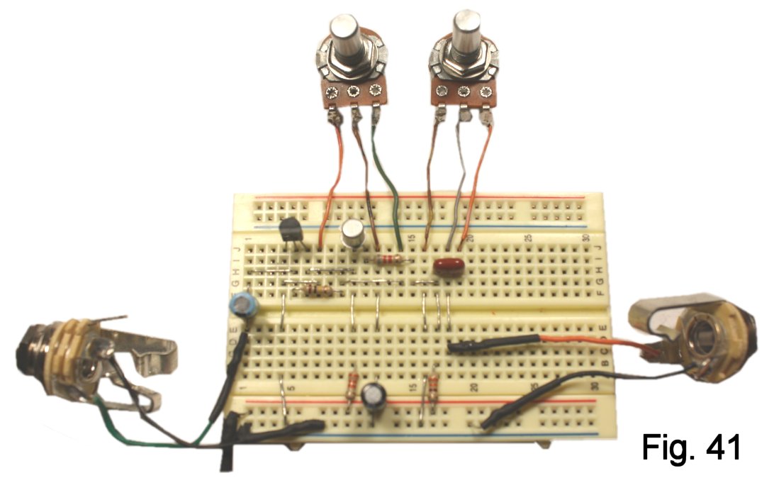
Prepare the fuzz and volume potentiometers for connecting to the breadboard by soldering leads to them. A few inches of insulated breadboarding wire to each terminal is fine. By convention, we refer to the terminals of the pots as CCW (counter-clockwise), W (wiper, for the moving contact) and CW (clockwise) (Figure 32).
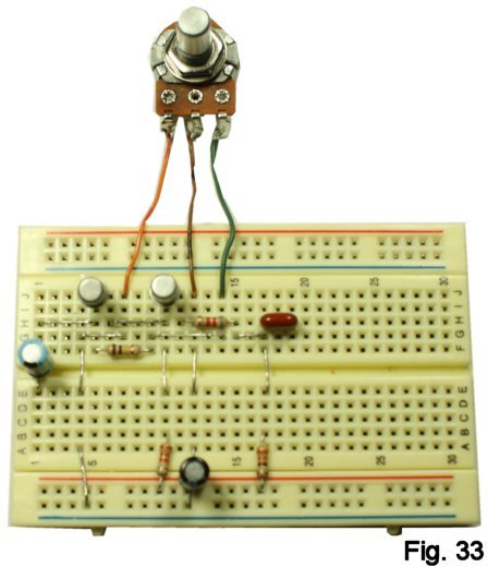
Add three jumpers: G-4 to G-7, G-9 to G-14 and E-12 to F-12. Then the connections to the fuzz pot are:
-
CCW to the ground bus
-
CW to index J-14
-
Wiper to index J-12
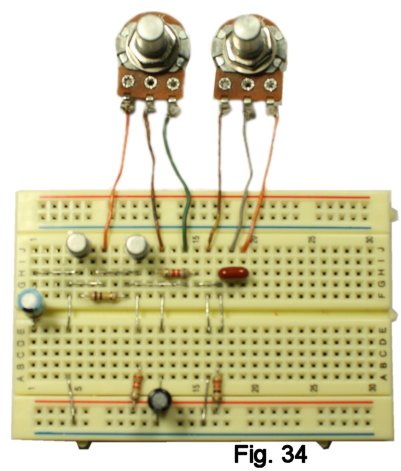
Then add the 22 mf. electrolytic capacitor from index A-12 to the ground bus. Negative side to ground, please! Check all of this out in Figure 33. Now add the level pot as shown in figure 34.
-
CCW to the ground bus. This needs two jumpers.
-
Wiper to index J-18
-
CW to index J-19
Figure 35 shows the additions.
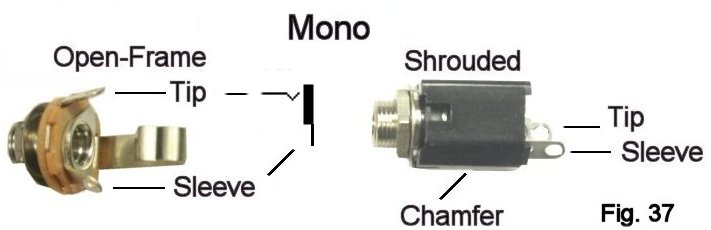
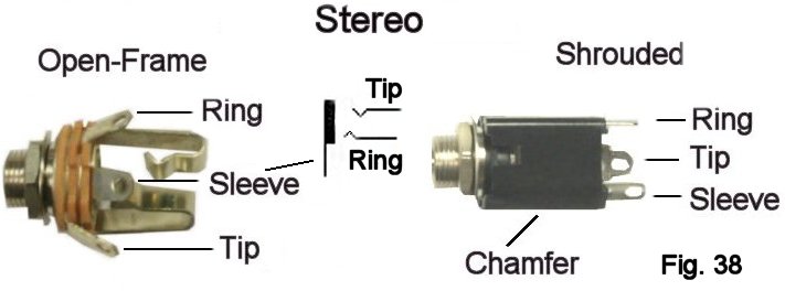
For testing purposes, we want to install input and output jacks as shown in Figure 36. The schematic shows mono jacks for both input and output. This type has two contacts: tip and sleeve. Figure 37 shows the relationship between the schematic symbol and two styles that you are likely to see, shrouded and open-frame. Figure 38 does the same thing for a stereo jack, which has three contacts: tip, ring and sleeve. The stereo jack shown is a Switchcraft #12B; note that the arrangement of the contacts may be different on other makes.
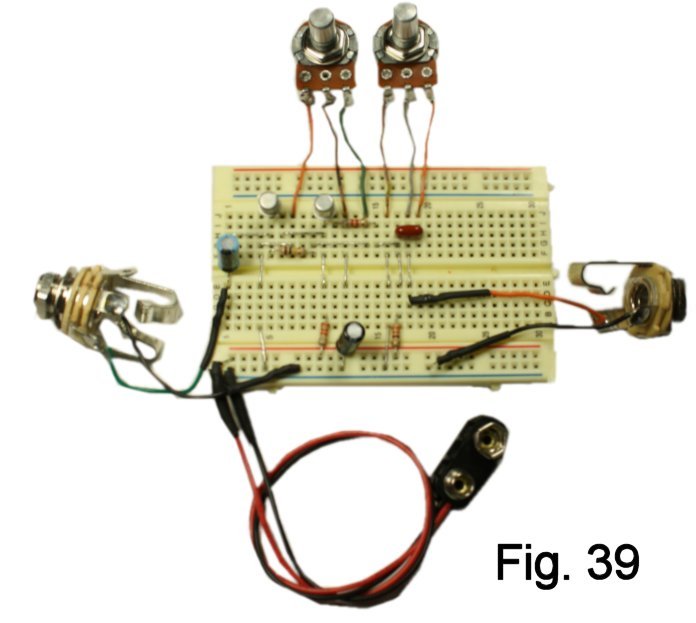
In a typical pedal build, we would use a stereo jack for the input and connect the ring contact to switch battery power. To keep things simple here, we use only the tip and sleeve. Connect short lengths of wire to each jack. The sleeves of both jacks are plugged to the ground bus. Input tip goes to index D-1, output tip to index D-18. That last connection needs a jumper to the wiper of the level pot. Things should look like Figure 39.
ARE YOU READY?? Connect your amp and connect a battery. Turn up the level control and turn up the fuzz pot till you hear fuzz. Try playing with it a bit.
Doesn't work? Go back through the pics and figure out what isn't connected right. Also be sure that:
-
All component values are correct
-
Polarities of the electrolytic caps are observed
-
Transistor pinouts are correct
I have built exactly as shown, and the instructions have been vetted by my assistant as well, so we are sure that your build will work if everything matches the instructions.
I Like The Way It Sounds...Now What?
You have gone far enough to build it on perfboard or PCB and put it in an enclosure for gigging! Or you can continue below if
-
You are working with the SBE kit, AND are sure you've wired correctly, but the tone is poor.
-
You are rolling-your-own and/or working with components that are not in the kit.
-
You want to try some mods, like a tone stack.
It works, But It Sounds Terrible!
If you are working from the kit, this should not be the case because the components have been pre-selected. Check your wiring!
Presuming there are no wiring errors, let's look at possible tweaks. Back in the day, Fuzz Faces had a deserved reputation for being variable in tone quality, and what you hear may be what many guitar players heard when trying them out. They would try many pedals till they found "the one" that sounded good. Since then, numerous people who are way smarter than I am (Thank You, R. G. Keen, Mark Hammer, and many others!) figured out exactly How the circuit works, and how to tweak it so that every build sounds consistently good.
Why Does The Fuzz Only Happen In The Last 10% of the Rotation?
"Taper" in potentiometers is the relationship between percent rotation and percent change in resistance. The 1K fuzz pot in the original Fuzz Faces was linear taper; a 10% change in rotation gives about a 10% change in resistance. Over time, a number of people noticed that an audio (left-hand logarithmic) taper gave much better control of the fuzz. But the direction of control was reversed, and so not intuitive; the greatest distortion was at the counterclockwise end. A pot with a reverse audio taper straightens this out, and that's what you get in my kit. If you are using a linear ("B") taper pot, change it out.
OK...But the Fuzz is Harsh or The Sound is Limp/Sputtery...
This is usually because the transistors are in the wrong gain buckets, not correctly biased or both. Transistors are as individual as snowflakes; no two are precisely alike. Even among devices that have the same type number, a variation in gain of three to one or more is not unusual. The BC108, for example, which I have seen specified in many old schematics for the silicon Fuzz Face, might have a gain of anywhere from 80 to over 200 depending on what factory made it and when. The problem is similar with any of the other NPN silicon devices that are commonly substituted for it.
Without going into the math that describes exactly why, it turns out that, for the standard resistor values that you will usually see in the Fuzz Face circuit, most people like the resulting sound when Q1 has a gain of roughly 70 to 90 and Q2 a gain of roughly 120 to 140. If both devices are very low in gain, the circuit is likely to sound lifeless; if both devices have gains of several hundred, it's likely to sound harsh. Part of the key to getting smooth clipping from the Fuzz Face circuit is selecting transistors that are in workable gain buckets. So...
Measure The Gains of Your Devices and Know What You Have!
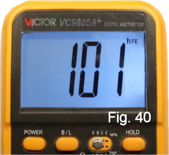
Today, even inexpensive multimeters usually have a scale for measuring transistor gain. The scale is usually labeled "Hfe", and it's plug-and-play. My first setup with two 2N2222A above didn't sound right, and no wonder; one device had a gain in the 50s and the other in the low 100s. This combination can actually be made to work, as we'll see later when we look at biasing. For now though, let's concentrate on finding a better match of gains.
The factory-specified gain range for the 2N2222A is 100 to 300; one of these falls right in the middle. At low 100s, it could be used. for Q1 or Q2. For test purposes, I stuck it in the Q2 position and looked for an alternate for Q1. Rather than trying to find a 2N2222A with an unusually low gain, I fished for a different NPN transistor that typically runs lower in gain according to the factory specs. One that I found I like is the 2N4123; I tested half a dozen samples from my stock using the gain scale of my multimeter, and they all measured between 80 and 90. With the 2N4123 in the Q1 position, the circuit sounded better, but still not "right". We're not done; need to line up the bias, and I'll get to that in a minute.
So what do you do if you are rolling your own? The good news is that many transistor type numbers will work in this circuit. They are also very inexpensive and readily available from many sources, both local and mail order. If you buy a few of several types, you will surely find at least two devices that will work well together. The basic specs are:
- Silicon, NPN
- Small signal
- low- to medium-gain, call it 60 or 70 to low 200s
The part numbers I suggest are: BC108, 2N2222A, 2N3904, 2N4123, 2N4401. You'll find other recommendations in previous threads at diystompboxes.com. Try a search on "silicon fuzz face." For puroses of testing and setup, here are some typical pinouts that you might run into:
FAQ: What if I really want to use germanium transistors?
Everything I said above about selecting devices applies to germanium as well. However, a multimeter Hfe scale won't read germanium devices accurately. Check out the method for testing gain in my article about Fuzz Face transistors. Also be aware that while NPN germanium suitable for the Fuzz Face is available, it's fairly scarce and so expensive. If you use PNP devices, polarities of battery and electrolytic capacitors must be reversed.
Adjusting The Bias
For good results, this circuit wants the collector of Q2 to be at about half the supply voltage, or roughly 4.5 volts. See figure 43. To make this measurement, set your meter to its low-voltage scale. You don't have to have the guitar connected, do need the battery plugged in. Connect the negative side of the meter anywhere on the ground bus, positive side to collector of the transistor. Figure 44 shows what I saw.
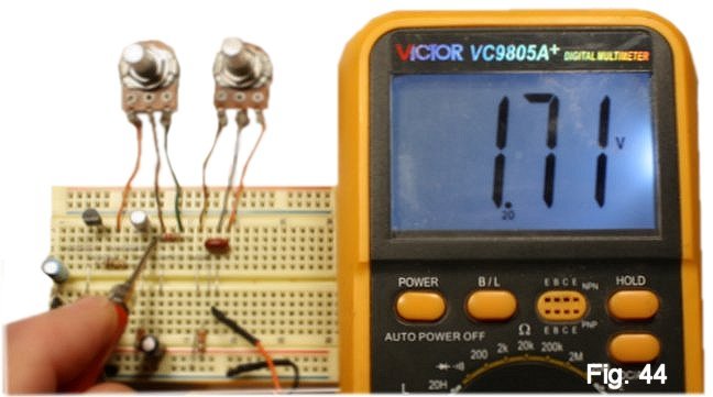
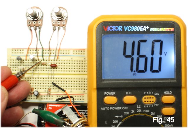
This is way too low, and it's no wonder that the sound is limp and unfocused. To put the collector voltage where it needs to be, we want to reduce the value of the 8.2K Collector load. This will cause more of the supply voltage to drop across the Collector-Emitter of Q2. I started substituting standard resistor values, and Figure 45 shows what things looked like with 5.1K in place of the original 8.2K.
When you have the bias close to 4.5 volts, try playing through circuit again. Now it sounds like a Fuzz Face, right?
Tweaking With a Trimpot
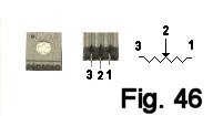
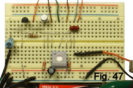
Sometimes you want to be able to tweak a little, play a little, etc., to see what difference a small change in bias makes. Trimmer potentiometers ("trimpots") are good for this. You can get them in a variety of case styles and a wide range of resistances. Figure 46 shows top and bottom views of one of my SKU 1015 cermet types (10K resistance) along with its schematic symbol. Figure 47 shows a trimpot set up to replace the resistor. When installing it on the breadboard, it does not matter whether you connect to pins 1 and 2 or 3 and 2. Start with the adjusting screw at about the halfway point before applying power.
Some builders just tweak the trimpot till they like the result; others connect the multimeter to measure the bias as before, set the trimpot to get exactly 4.5 volts, and then experiment from there. You might then measure the resistance of the trimpot using your multimeter and substitute the closest value fixed resistor, 1% tolerance if you want to get really anal. Or leave the trimpot in. It's your build...
One last suggestion, this one from Phil Bryant's Fuzz Central: a small capacitor, from 100 to 500 pf., between the Base and Collector of Q1 or Q2; tames raspiness but doesn't decrease definition. It's especially useful when you are using very high gain transistors. I'm not photographing this, because you should be able to add it on your own now.
At this point, even if you are rolling-your-own, you should have a result on the breadboard that is good enough to commit to solder. So now build it on perfboard or PCB. I'm purposely stopping short of suggesting mods, because I want to keep this version as simple as possible. Future builds will include features like a tone stack, pre-gain control, and others. I hope you have enjoyed learning to breadboard the Fuzz Face. Comments and suggestions are welcome at smallbearelec@ix.netcom.com.
A Parts List
Here is everything needed to do all of what I have described, including the LED demo in the intro article. A kit containing all of this is available as SKU 0010.